Failing External CFD: What It Means, Why It's Increasingly Common, and Why the Fix Belongs in the Original Design
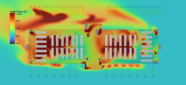
Every critical facility design includes an external computational fluid dynamics (CFD) model of the mechanical yard — the air-cooled chillers, dry coolers, generators, and switchgear sited outside the building. The model simulates how that equipment performs when adverse conditions stack on top of each other: high ambient temperature, unfavorable prevailing wind, hot air recirculation between units, and even the loss of a utility feed, all occurring simultaneously. The output is a heat map showing the entering air temperature at each air-cooled chiller's condenser (or dry cooler)inlet under that coincidental, worst-case scenario.
This is a Murphy's Law approach to engineering necessary for critical facilities: assume that everything that can go wrong will go wrong, and at the same time, then confirm the site can still deliver full cooling capacity anyway. If a facility is engineered to withstand that condition —commonly called the design day — it can theoretically navigate any lesser combination of conditions encountered in actual operation. We've written before about why design day analysis and Peak PUE are the foundation of how critical facilities are sized, and the external CFD is the tool that proves the design will hold up under that standard before a shovel goes into the ground.
What does a "failing" CFD actually mean?
An external CFD result is generally considered a failure under one of two definitions, and they often show up together.
1. Loss of critical cooling capacity. The entering air temperature at the condenser inlet, driven up by the combination of high ambient temperature, wind-driven recirculation, and equipment spacing constraints, exceeds what the chillers can handle at full rated output. Capacity degrades, head pressure climbs, and in the worst cases units trip offline entirely — the exact failure mode we've detailed in the context of high-density heat rejection.
2. Exceeded utility allocation. Even if the chillers stay online, they have to work harder — higher compressor load and higher amp draw — to deliver the required capacity against that elevated entering air temperature. That additional electrical draw can push the chiller plant's total demand beyond the substation capacity. This type of failure is most common with high-ambient centrifugal chiller configurations. They push thermal boundaries upward, but at a steep price in terms of compressor power draw.
This kind of CFD failure is just as disqualifying as the loss of critical cooling capacity.
Either definition is enough to send a design back to the drawing board. Increasingly, both show up in the same model, because the same environmental stack that spikes entering air temperature is also what drives compressor power upward.
A leading 500 nominal ton centrifugal chiller can provide nameplate cooling capacity up to 130°F CEAT (Condenser Entering Air Temperature). However, it pulls ~35kW more power for every 5°F increase in CEAT. So input power increases approximately 140kW per chiller from 110°F to 130°F CEAT. Extrapolated across a 50-chiller plant, that equates to over 7MW of power that must be allocated (i.e. stranded) for these fringe peak conditions.
Why failing CFDs have become commonplace
External CFD failures used to be the exception. They're now routine, for two related reasons.
The first is densification. GPU-driven compute densities have pushed power draw per rack up by an order of magnitude, while the physical footprint of most data halls hasn't grown to match. That means far more waste heat must be rejected from the same building envelope — a dynamic we've walked through in detail when discussing heat rejection challenges in high-density design. Heat rejection technology outside the building has not kept pace with the innovation happening inside the data hall.
The second is the sheer size of the data centers, and therefore the chiller plants required to reject that heat. Air-cooled chillers need adequate spacing to avoid recirculating the same heat they're designed to expel, but larger plants packed onto constrained rooftops or yards increasingly can't get that spacing. The equipment yard develops its own microclimate, running 15–40°F hotter than surrounding ambient air during full load —precisely the recirculation effect that turns a marginal CFD result into a failing one. (For more on how these plants are classified and where water enters the picture, see our breakdown of air-cooled versus water-cooled terminology.)
Adiabatic precooling is the proven mitigation
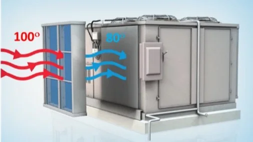
Peak+ adiabatic precooling addresses both failure modes directly. By precooling the ambient air before it crosses the condenser coil, the system can reduce entering air temperature by as much as 40°F. Lower entering air temperature preserves rated cooling capacity under design day conditions, which resolves the first failure mode, and it reduces compressor head pressure and amp draw at that same peak hour, which resolves the second. This isn't a theoretical fix — it's the same mechanism we've detailed for air-cooled chillers and large rooftop units, applied at the scale a data center chiller plant demands.
Don't wait for the CFD to fail — design it in from the start
The common pattern is to treat adiabatic precooling as a rescue plan: the external CFD comes back with a red zone on the heat map, and precooling gets bolted on to fix it. That sequencing is backwards, and it leaves value on the table.
If suppressing peak entering air temperature is treated as a baseline design parameter from day one, rather than a late-stage remediation, the chiller plant and its electrical infrastructure can be sized around that controlled, lower peak — not around the uncontrolled worst case. That has a direct commercial consequence. The amount of revenue-generating IT load a site can support is capped by whatever electrical headroom is left over aftercooling load is accounted for at design day. Lower the peak cooling load, and more of the available power budget can be allocated to IT rather than oversized cooling margin. It also limits operating expenses because utility demand and capacity charges are set by peak power draw.
We've quantified exactly what that trade-off is worth: at a 300 MW site, lowering peak PUE by just 10% can free up roughly 22 MW for IT load — using the identical capital equipment, just engineered around a controlled rather than uncontrolled peak. Our 55MW Nevada data center case study shows this isn't hypothetical: suppressing peak temperature constraints let the operator switch from water-cooled to air-cooled heat rejection without exceeding the utility electrical allocation.
Engineers and owners who wait for a failing external CFD to justify adiabatic precooling are solving yesterday's problem. The ones who design around a controlled peak from inception are capturing tomorrow's capacity.